Ring the Bell Goes IRL

Hunter Fernandes
Software Engineer

Our #ring-the-bell channel in Slack. We added percentile milestones reflected with champagne and koolaide emojis, a cultural meme from the very early days.
One of the things I did early on at my startup was set up a #ring-the-bell channel in Slack. The idea was that whenever we had a new customer, our software would automatically post a message in the channel. It was a fun way to celebrate our successes and keep the team motivated.
But you know what’s even more fun than a Slack message? A physical bell that rings! This is the kind of absurd thing that I thought would make a great winter project.
Designing the Electronics
I am a pure software person. I know literally nothing about electronics, so I started by doing some research. I wanted some assurance that I was not going to electrocute myself, so I bought the wonderful book Practical Electronics for Inventors and skimmed through it. My takeaways were:
- This would be fairly simple circuit-wise,
- I should avoid mains power. This is fine because this is just an IoT project.
I figured I would want:
- A Raspberry Pi to run the software, connect to the internet, and control the bell. Adafruit has the Zero W, which is a Raspberry Pi Zero with built-in WiFi and Bluetooth.
- A solenoid to physically drive the bell plunger.
- A MOSFET to drive the solenoid from the Raspberry Pi. I need one of these because the solenoid draws more current than the Raspberry Pi can provide. Instead, the Raspberry Pi will send a signal to the MOSFET, which will then switch the solenoid on and off.
- The Raspberry Pi official USB-C power supply. I don’t want to deal with mains power, and it seems like good U/X to just plug the USB-C cable into the Raspberry Pi.
- A USB-C power connector. I need a way to connect the Raspberry Pi to the power supply. I found a USB-C power connector at Adafruit that I could solder to the solenoid. This will output a 5v line and a ground line that I can connect to the Raspberry Pi and the MOSFET.
Everything else is just details. I am very comfortable with software, so I decided to put off the Raspberry Pi until I had the hardware working.
I picked an EDA tool and started designing the circuit. I decided to go with EasyEDA because it is free, had a ton of components in its parts library, and was easy to use. I am a noob, so having everything packaged in one tool was a big win.
Prototype Circuit
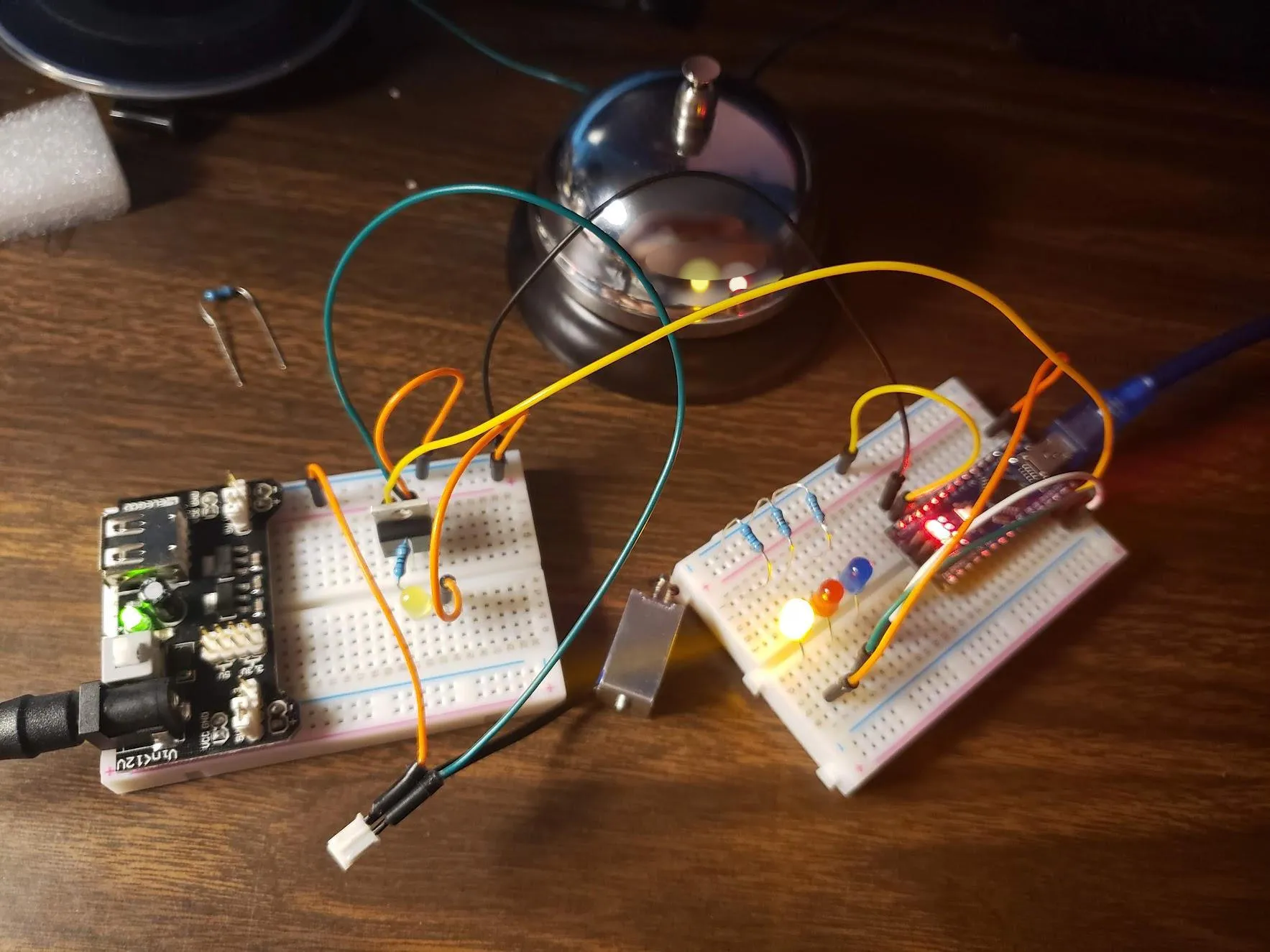
Let’s prototype this thing! This has just a power supply, a switch, a solenoid, and a MOSFET. I used a breadboard to prototype the circuit. I added a pulldown resistor to the MOSFET gate to ensure that it is off when the Raspberry Pi is not driving it.
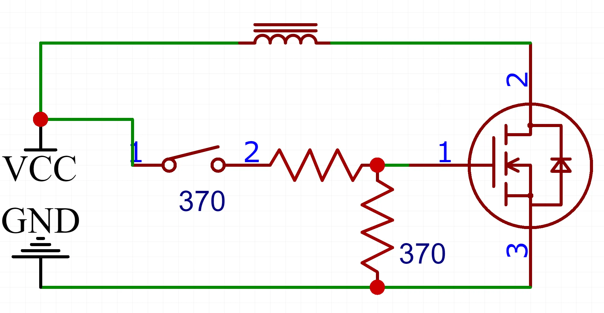 | 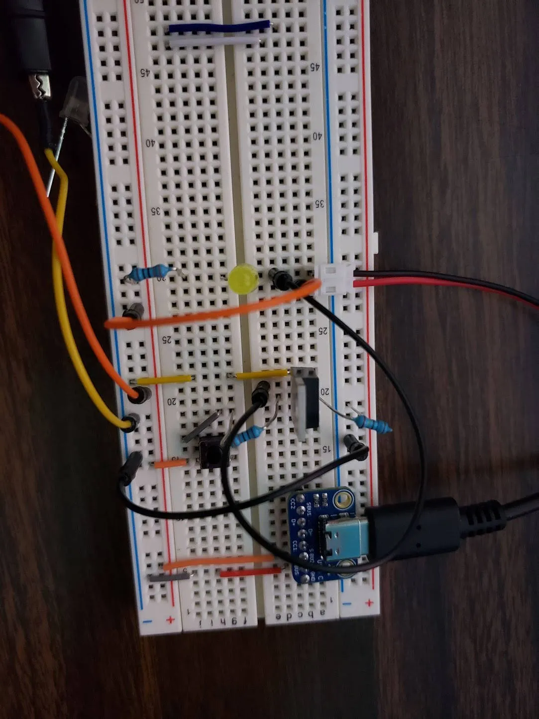 |
And this is when I had my first issue.
Voltage Drop
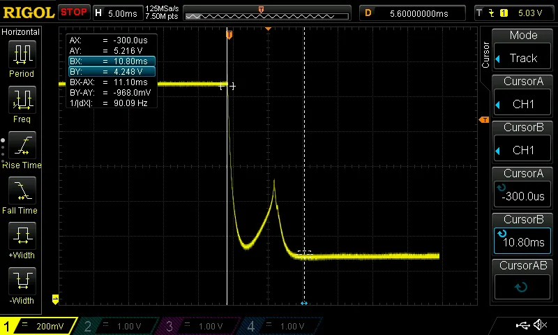
The voltage drop across the USB-C power supply when the solenoid is on.
Did I mention that I bought a Rigol DS1054Z oscilloscope? It’s a great tool for debugging electronics. The value is great!
The USB-C power supply was providing a nice 5.2V, but when the solenoid was activated, the voltage dropped to 4.25V. This drop of almost 1V would be bad for the Raspberry Pi — at best it would cause a reset. Electronics don’t like it when the voltage is too low — they can’t operate correctly. For fear of frying the Raspberry Pi, I switched to an Arduino for the time being.
This voltage drop made no sense at all. I double checked the power supply, the USB-C connector, and the wiring. It should have worked.
Debugging the Voltage Drop
I put a capacitor across the power line to smooth out the voltage drop, and it did nothing. Some googling suggested that the power supply was not able to provide enough current that fast. This is called transient response time and it would make sense because my power supply is for electronics and not for driving a solenoid. Alas, the capacitor did nothing.
While electronics can sure feel like magic, it’s not. So let’s get down to the basics and start debugging by isolating the problem.
I tried all combinations of:
- Power Supplies: Raspberry Pi USB-C power supply, Apply Mac USB-C power supply
- Cables: Official USB-C cable, Apple USB-C cable
- USB-C board power: Adafruit USB-C breakout, Sparkfun USB-C breakout

The USB Power Delivery spec for current advertisement. Spoiler alert: this was not the problem.
The Apple power supply can give up to 100W, so I thought it would be a good test. However, it had the same issue.
I even ended up reading a copy of the USB Power Delivery spec to understand how the power negotiation works. I thought that maybe my circuit was not negotiating the right power level with the power supply and then drawing too much current. Using my oscilloscope, I could see that the protocol was negotiating the right power level. So it’s not that.
In a moment of clarity, I realized that the only common component in all of these tests was the breadboard. In fact, I had bought the cheapest breadboard I could find on Amazon. I swapped it out for a better quality breadboard, and the voltage drop disappeared. The cheap breadboard I was using could not support the current draw of the solenoid.
Lesson learned: don’t skimp on the breadboard.
Project Review
At this point, I stopped and took a look at the project. I had a few notes for myself from working on the prototype, and I made the following two changes:
Flyback Diode
Reading about the solenoid led me to the concept of a “flyback diode.” A solenoid is an inductive load — essentially a big magnetic field. When you turn the solenoid off, the magnetic field collapses, creating a negative voltage spike. This is very bad for microelectronics (like the Raspberry Pi) or a MOSFET. It can fry them.
In order to fix this, we add a diode across the solenoid. When the solenoid is on, the diode is reverse-biased and does nothing. When the solenoid is turned off, the magnetic field collapses and creates a negative voltage spike. Our diode shorts this spike to ground, protecting the rest of the circuit.
Capacitance
The rapid switching of the solenoid and MOSFET can also create a lot of noise on the power line. This is also bad for the Raspberry Pi. I added a capacitor to smooth out the power line.
My oscilliscope showed that adding even a small capacitor across the power line smoothed out the power line substantially.
Tweaks for the MVP
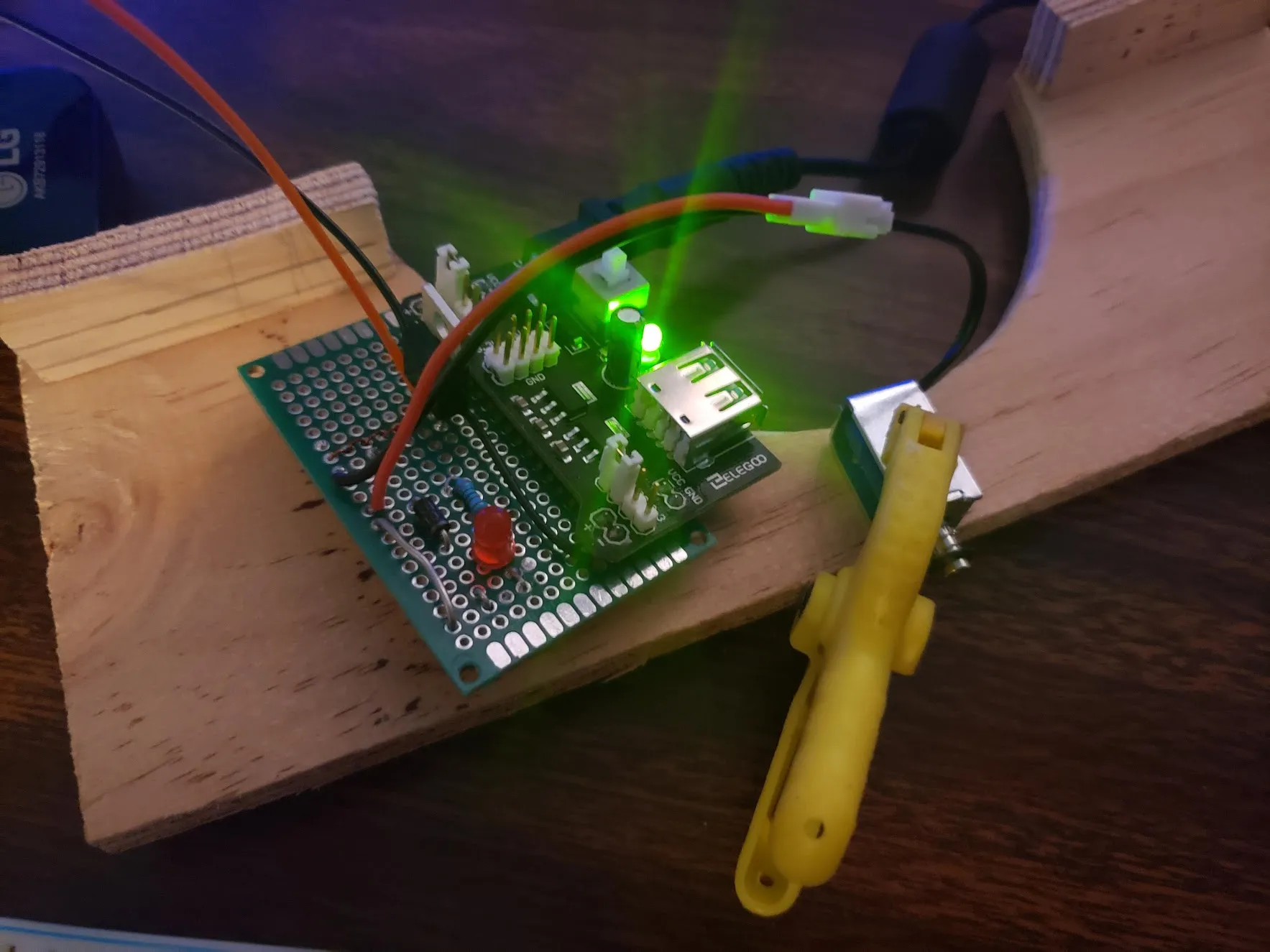
I wanted to get an MVP working as fast as possible for a demo, so I removed the USB-C power supply and breakout board in favor of a barrel jack and associated power supply. The USB-C breakout board required soldering to something and I wasn’t sure how I wanted it to look yet.
I soldered down the components to a perfboard and got the Arduino working with the solenoid. My MVP was ready!
Mounting It

This is the fast sketch I made for the bell mount. MS Paint, folks.
Before I continued with the electronics, I wanted to figure out how I was going to mount this thing. I thought the easiest thing to do was a 3D printed mount. But I don’t have a 3D printer and I had already used a lot of “innovation tokens” on this project.
I therefore decided to go with tried and true methods: wood and screws. My dad is a carpenter, after all.
Cutting the mount to shape.
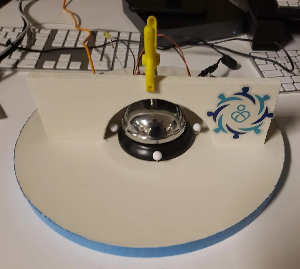
My rough idea was a circular base with a vertical arch, under which the bell would sit. The solenoid would be mounted to the arch and the plunger would hit the bell.
I went to Friedman’s, my local hardware store, and picked up a round, thick wooden base, a small rectangular piece of wood, and some paint.
After cutting out an arch and making some feet for the base, I painted it all white and slapped a logo on it. Then I mounted the solenoid to the arch and the bell to the base. Finally, I stuck a pin into the wood so the electronics would not shift too much.
Looks great for an MVP!
I knew two things right away:
- It needed to have a quiet time. We don’t want it ringing at 3AM when nobody is in the office.
- It was kind of ugly. The eletronics were just hanging out the back. I’ll have to fix that later.
- I wanted more LEDs. Namely, a network indicator, a poll indicator light, and a sleep indicator light.
Either way, it was time to make it functional.
Writing the Software
Now that I had all the electronics working, I could move on to the software. I did this late into the process because the software should be easy.

The pinout for the Raspberry Pi Zero W available from pinout.xyz. I stared at this a lot.
I have a Raspberry Pi Zero W, which is a Raspberry Pi Zero with built-in WiFi and Bluetooth. This is important because I need to connect to the internet. The Zero W has the same standard GPIO pins as the Raspberry Pi, so it should be well supported.
All I need to do is listen to something on the internet and then fire GPIO pins. I decided to keep it simple and have the client poll.
The Backend
I am a cloud engineer, so naturally I decided to do the backend first.
How is this thing going to work? It’s best to start with the architecture. Let’s create an “API” that the Raspberry Pi can call to get the bell count. I think it’s best to use a Lambda for this, as it’s a simple function that can be called from the internet that we can trust to access the Redis instance.
There are quite a few benefits to this approach:
- Abstraction: The client does not know the details of where the counter is stored. We effectively give it the “API” of calling a function and getting a number back.
- Network Security: Redis, like the rest of our infrastructure, is in a VPC that cannot be accessed from the public internet. We don’t want to expose Redis to the internet. Instead, the Lambda function can be in the same VPC and have access to the Redis instance.
- Client/Server Separation: Having the Lambda function in the middle allows us to write trusted code that can access Redis. The client should always be trated as untrusted. Our Raspberry Pi could be compromised, and we don’t want it to have access to Redis containing other customer data.
- Enrichment: We can add metadata to the response, like “quiet hours.” This gives us a point where we can augment the functionality of the bell. Normally, I would break up functionality into multiple “APIs,” but this is a small project and to keep it simple, I put it all in one function. Consequently, we are going to overload the GetRingCount API to get more than just the count.
The Lambda Function
Our Lambda will need a dedicated Redis user to access the Redis instance. We can create that using Elasticache’s user management and we’ll restrict it to only be able to read the bell counter, rtb/ring-the-bell-count.
aws elasticache create-user \
    --user-id ring-the-bell \
    --user-name ring-the-bell \
    --access-string "on ~rtb/ring-the-bell-count -@all +get" \
    --password "hunter2"
Let’s stick the Redis password in Secrets Manager, as we don’t want to hardcode it in the Lambda function.
aws secretsmanager create-secret \
    --name ring-the-bell-redis \
    --secret-string '{"username": "ring-the-bell", "password": "hunter2", "hostname": "master.my-redis-cluster.abcd.usw2.cache.amazonaws.com"}'
After creating the IAM Policy and Role, next we’ll create the Lambda function. Usually we would use Cloudformation or Terraform, but this is a small project.
aws lambda create-function \
    --function-name ring-the-bell-api \
    --runtime python3.9 \
    --role arn:aws:iam::12345678:role/lambda-role \
    --handler lambda_function.lambda_handler \
    --vpc-config SubnetIds=subnet-12345678,SecurityGroupIds=sg-12345678, \
Fortunately for us, Redis is dead simple. It’s just TCP, TLS, and a simple text protocol. We don’t even need a Redis client library for this. This allows us to use the default code editor in the Lambda console, as we do not need to include any custom packages.
import json
import socket
import ssl
import time

import boto3

secret_value = json.loads(
    boto3.client('secretsmanager').get_secret_value(
        SecretId='ring-the-bell-redis',
    )['SecretString']
)

username = secret_value['username']
password = secret_value['password']
hostname = secret_value['hostname']

def lambda_handler(event, context):
    port = 6379

    context = ssl.create_default_context()

    with socket.create_connection((hostname, port)) as sock:
        with context.wrap_socket(sock, server_hostname=hostname) as ssock:
            ssock.send(f'AUTH {username} {password}\r\n'.encode())
            data = ssock.recv(128)

            ssock.send(b'GET rtb/ring-the-bell-count\r\n')
            resp = ssock.recv(128)
            rings = int(resp.split(b'\r\n')[1])

            resp = {
                'RingCount': rings,
                'QuietTime': '7PM - 6AM (America/Los_Angeles)',
            }
            return resp
Finally, let’s create an IAM user for our client.
aws iam create-user --user-name ring-the-bell-client
aws iam create-access-key --user-name ring-the-bell-client
# { "AccessKey": { "AccessKeyId": "AKIAABC", "SecretAccessKey": "XX" } }
We’ll copy the AccessKeyId and SecretAccessKey into the Raspberry Pi’s ~/.aws/credentials file later.
That should do it! Let’s test it out.
AWS_ACCESS_KEY_ID=AKIAABC \
AWS_SECRET_ACCESS_KEY=XXX \
aws lambda invoke --function-name ring-the-bell-api /dev/stdout

# {"RingCount": 123, "QuietTime": "7PM - 6AM (America/Los_Angeles)"}
Backend done, let’s move on to the frontend.
The Frontend
Let’s write the code for the Raspberry Pi. I decided to go with Go because it’s a compiled language and I can cross-compile it for the Raspberry Pi. This means I can write the code on my laptop, compile it, and send the binary to the Raspberry Pi. Plus, I have an interest in it and I wanted to get better at it.
I decided to use github.com/stianeikeland/go-rpio package, as it’s small and popular. I just need to turn pins on and off, nothing terribly complicated.
The first thing I did was wrap the hardware pin interface so that I can run the code on my laptop.
package main

import (
	"fmt"
	"github.com/stianeikeland/go-rpio"
	"runtime"
)


var (
	hasInitializedPins bool = false // we only need to globally initialize hardware pins once
)

// Pin is anything we can set to low or high. We want to wrap
// both RPi's physical pins as well as our software virtual pins for testing.
type Pin interface {
	High()
	Low()
}

// GetPin Returns a logical pin you can use.
// It might be a hardware pin, might be a software pin.
func GetPin(pinNo int) Pin {
	if IsRPi() {
		if !hasInitializedPins {
			err := rpio.Open()
			if err != nil {
				panic(err)
			}
			hasInitializedPins = true
		}

		pin := rpio.Pin(pinNo)
		pin.Output()
		pin.Low()
		pin.PullDown()
		return &pin
	} else {
		pin := &VirtualPin{PinNo: pinNo}
		pin.Low()
		return pin
	}
}

// VirtualPin is our software implementation of a pin
// for when we are running on a Mac (not the RPi)
type VirtualPin struct {
	PinNo int
}

func (v *VirtualPin) High() {
	fmt.Printf("(Pin%d=1)", v.PinNo)
}

func (v *VirtualPin) Low() {
	fmt.Printf("(Pin%d=0)", v.PinNo)
}

func IsRPi() bool {
	return runtime.GOOS == "linux" && runtime.GOARCH == "arm"
}
I decided to take advantage of Go’s concurrency support to have my architecture have several “pollers” that would lead to a ring. Really, this is a reactive architecture, with a main loop and different goroutines that feed events into it.
- An AWS Poll loop, which polls the AWS API for the bell count. This creates
RINGevents. - A file poll loop, which polls a file for a
RINGevent. This is for testing. - A keyboard poll loop, which can take commands for a REPL and create
RINGorQUITevents.
// StatsApiResponse is the structure we get from calling
// the "signup stats API" which is just code written in an AWS Lambda.
// We do this to enforce a security boundary.
type StatsApiResponse struct {
	RingCount int    `json:"RingCount"`
	QuietTime string `json:"QuietTime"`
}

func getCount(client *lambda.Lambda, sm *SleepManager) (int, error) {
	pinset.AwsPoll.High()
	raw_resp, err := client.Invoke(&lambda.InvokeInput{
		FunctionName: aws.String("ring-the-bell-api"),
	})
	pinset.AwsPoll.Low()

	if err != nil {
		return 0, err
	}

	probe := StatsApiResponse{}
	if err := json.Unmarshal(raw_resp.Payload, &probe); err != nil {
		pinset.Network.Low()
		return 0, err
	}

	if probe.RingCount == 0 {
		pinset.Network.Low()
	} else {
		if sm != nil {
			sm.SetConfiguration(probe.QuietTime)
		}

		pinset.Network.High()
	}

	return probe.RingCount, nil
}

func awsPollLoop(lambdaClient *lambda.Lambda, ringRequests chan BellRingParameters, sm *SleepManager) {
	stepCount, err := getCount(lambdaClient, sm)

	for {
		newStepCount, err := getCount(lambdaClient, sm)

        if err == nil {
            if newStepCount > stepCount {
                for additionalRings := newStepCount - stepCount; additionalRings > 0; additionalRings-- {
                    ringRequests <- BellRingParameters{Source: "AWS"}
                }

                stepCount = newStepCount
            }
        } else {
            log.Println("Warning -- API request failed. Skipping rings.", err)
        }

		if sm.IsSleeping(time.Now()) {
			pinset.Sleep.High()
		} else {
			pinset.Sleep.Low()
		}

		time.Sleep(3 * time.Second)
	}
}
Next, we have our main loop, which listens for events and activatges the solenoid pin.
package main

import (
	"github.com/aws/aws-sdk-go/aws"
	"github.com/aws/aws-sdk-go/aws/session"
	"github.com/aws/aws-sdk-go/service/lambda"
	"log"
	"os"
	"os/signal"
	"time"
)

var (
	RingFlagFile = "/dev/shm/ring.flag"
	pinset       = Pinset{}
)

type BellRingParameters struct {
	Source string
}

type Pinset struct {
	Solenoid Pin
	AwsPoll  Pin
	Network  Pin // Network indicator light
	Sleep    Pin // sleep-mode indicator light
}

// ringTheBell fires the solenoid and physically rings the bell
func ringTheBell(source string) {
	log.Printf("The bell has been rung (%s)!\n", source)
	defer func() { pinset.Solenoid.Low() }()

	howManyDings := 3
	dingSeparation := 150 * time.Millisecond

	for i := 0; i < howManyDings; i++ {
		pinset.Solenoid.High()
		time.Sleep(30 * time.Millisecond)
		pinset.Solenoid.Low()
		time.Sleep(dingSeparation)
	}

	time.Sleep(1 * time.Second) // enforce duty cycle
}

func initializeLambdaClient() *lambda.Lambda {
	sess := session.Must(session.NewSessionWithOptions(session.Options{}))
	lambdaClient := lambda.New(sess, &aws.Config{Region: aws.String("us-west-2")})

	return lambdaClient
}

func main() {
	setupFlagFile()
	lambdaClient := initializeLambdaClient()
	sleepManager := SleepManager{}

	ringRequests := make(chan BellRingParameters)

	pinset.Solenoid = GetPin(23)
	pinset.AwsPoll = GetPin(24)
	pinset.Network = GetPin(25)
	pinset.Sleep = GetPin(16)

	// Initialize by setting network indicator off
	pinset.Network.Low()

	go awsPollLoop(lambdaClient, ringRequests, &sleepManager)
	go filePollLoop(ringRequests)
	go keyboardPoll(ringRequests)

	for params := range ringRequests {
		if !sleepManager.IsSleeping(time.Now()) {
			ringTheBell(params.Source)
		}
	}
}
I compiled the code on my laptop and copied it to the Raspberry Pi. I also moved the ~/.aws/credentials file over.
It worked great. I could ring the bell from the AWS API and watch my multimeter to see the pin go high.
Making it a PCB
At this point, I had the software done, the electronics done, and the mount done. But I thought it was ugly. So I decided to make a PCB for it! That would make it look more professional. I got the idea for this from watching Strange Parts by Scotty Allen, where he toured a PCB factory in Shenzhen. In the video he said they had a great deal for new customers, so I decided to give it a shot.
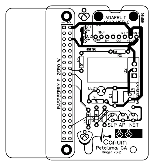
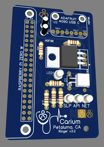
The first thing I did was redesign the circuit in EDA to include the Raspberry Pi, my status LEDs, and a flyback diode.
You can see that the pin numbers in the Go code match the GPIO pin numbers on the Raspberry Pi.
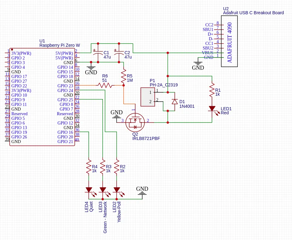
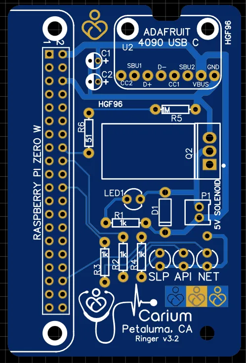
EasyEDA has a PCB design tool that is free and easy to use. Once again, the massive part library was a huge win for me. I could import the parts I used in my prototype and lay them out on a board. This made it easy to see how everything would fit together.
I used a 2-layer board, as it was the cheapest option and I didn’t need more than that. I was fine with through-hole components, as I was going to solder them by hand. They are easier to solder than surface mount components and I am still a noob. One thing I learned was the having a big ground plane on the bottom layer is a great idea, it makes terminating the ground connections easy.
I decided to have a motherboard/daughterboard design. This would allow me to use the PCB as the surface to mount the Raspberry Pi and USB-C breakout board. Visually, this also looks nice.
From experimenting with the breadboard, I was also cautious about the power line, so I made it as wide as possible. There is an online calculator for this, and the power lines are still not that big. It really makes me wonder what kind of crap breadboard I was using.

A photo of a Highland Cow hanging in our office. Frequently mistaken for a Yak, the plaque reads: “Aye Yak” / Breed: Highland Cattle.
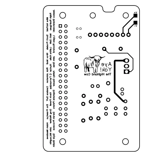
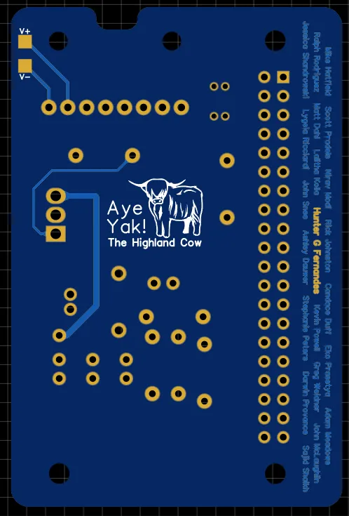
I went kind of crazy with the silkscreen, adding a logo and some text. I also added an internal meme to the board and the logo/earphones motif, which is a fun easter egg. Additionally, I added routes in the shape of a bunch of early employee names. I left them uncovered with soldermask, so they are shiny and visible.
Finally, I cut out some screw holes to mount the PCB to the wood base. Additionally, I cut out a divot for the USB-C connector to sit in. I was worried abuot clearance, so I made it as big as possible.
Our of all of the parts of this project, I spent the most time on the PCB. I wanted it to look good.
Top View | Bottom View |
|
|
|
|
EasyEDA has a 3D viewer that is really cool. They have 3D models of most of their parts. This means I can get a sneak peek of what the board will look like. | |
Now that I was happy with the design, I ordered the PCBs from JLCPCB. They have a great deal for new customers where you can get 5 boards for $2. My boards were half sized, and EasyEDA includes a small panelization export option where they can duplicate the design to fill a board. After submitting your design to JLCPCB, they will further panelize the boards for you, so in total I got 10 copies of the board. As long as you work within their design rules, it’s a great deal.
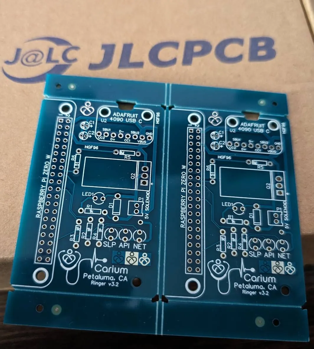
The PCBs arrived! They look great.
I got an email saying my design was approved and processed, and the next day I got an email saying they were printed and shipped. 7 days and a DHL logistics trip later, I had my boards in hand. It is really magical to see your design come to life like that.
As I noted earlier, I had manually panelized the boards into pairs of two. This meant I had to snap them apart myself. In hindsight, I should have made the scores deeper, as it was a bit of a pain to snap them apart.
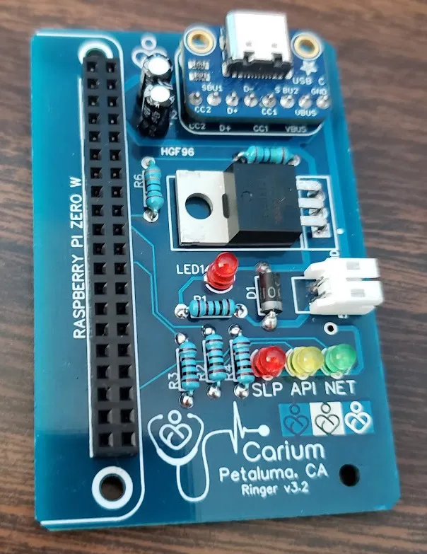
The PCB with all the components soldered on.
I soldered the components on by hand. This went better than I expected, as I had practiced on the prototype as well as some other small projects.
Putting it All Together
I swapped the completed PCB into the bell mount and connected everything up. I entered the public office WiFi credentials into the Raspberry Pi and booted it up. And it worked! Whenever a new customer signed up, the bell would ring. This provided a huge morale boost to the team, and we jokingly referred to it as our “first hardware product.”
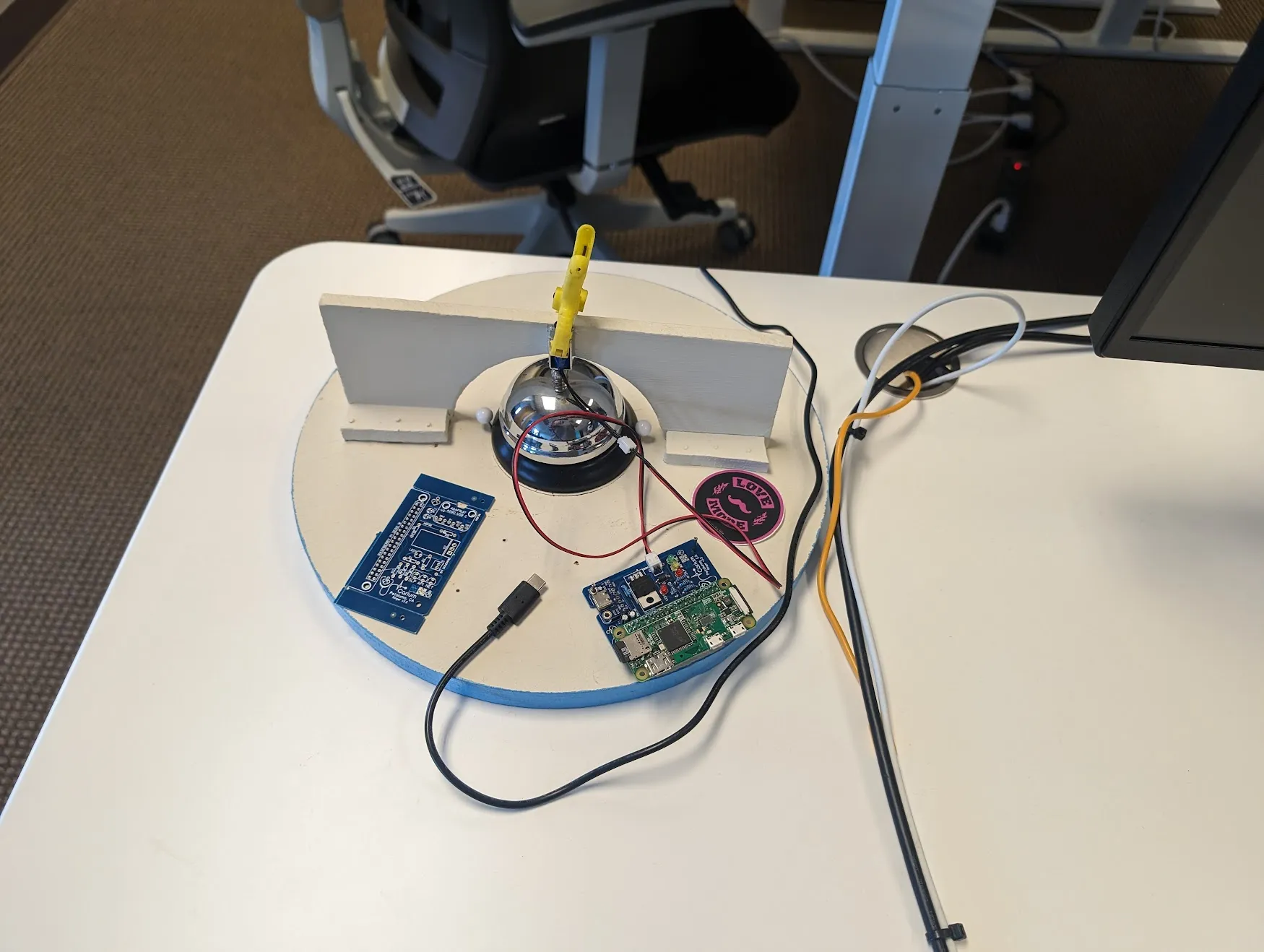
I left an empty PCB on the bell mount as a conversation piece. The quiet hours worked great and people no longer had to worry about unplugging the bell at night.
I was really happy with how this project turned out. It was a great learning experience and a fun project to work on. I learned a lot about electronics, PCB design, and even a bit of carpentry. I also got to use Go to interface with hardware, which was a lot of fun.
The bell became a central conversation piece in the office. The bell would speak for itself whenever we’d have guests (or investors) in the office. I think it “grounds” our world of in-the-cloud SaaS software to the physical world and gives our successes a voice.
Total Cost
This project came in at under $40. That’s a great deal!
| Part | Price |
|---|---|
| Raspberry Pi Zero W | $10.00 |
| Mini Push-Pull Solenoid - 5V | $4.95 |
| N-channel power MOSFET - 30V / 60A | $2.25 |
| USB-C power connector | $7.95 |
| USB-C Breakout Board | $2.95 |
| Diode, Capacitors, Resistors | $0.50 |
| Wood Base | $5.00 |
| Wood Arch | $2.00 |
| Total | $35.60 |
